


Konsultacje dotyczące produktu
Twój adres e-mail nie zostanie opublikowany. Wymagane pola są zaznaczone *


Przewodnik po szczotkowanych silnikach prądu stałego: jak to działa, najważniejsze dane techniczne i kiedy ich używać
Jun 04,2026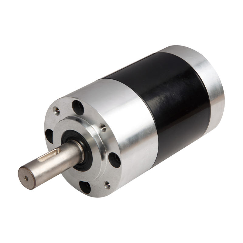
Motoreduktory prądu stałego: kompletny przewodnik dla kupujących dotyczący typów, specyfikacji i wyboru
May 28,2026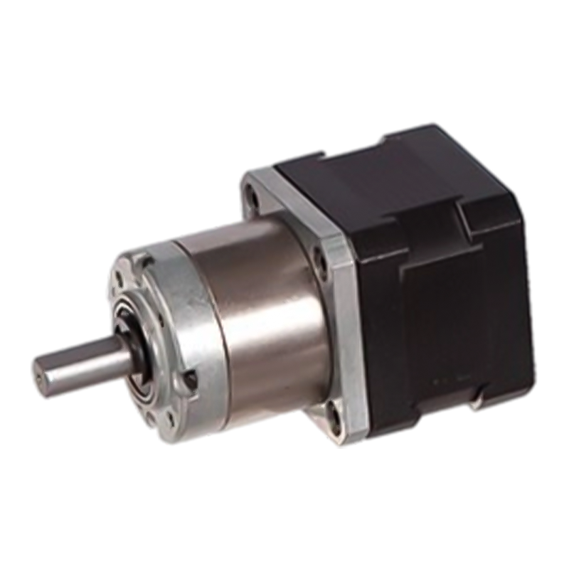
Wyjaśnienie motoreduktora krokowego: rodzaje, moment obrotowy i sposób wyboru właściwego
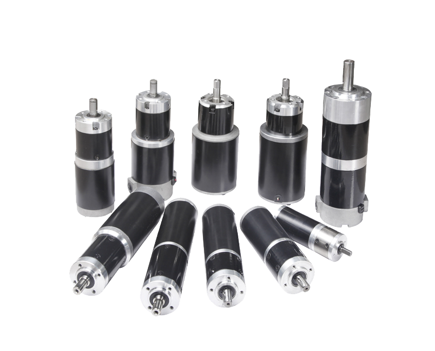
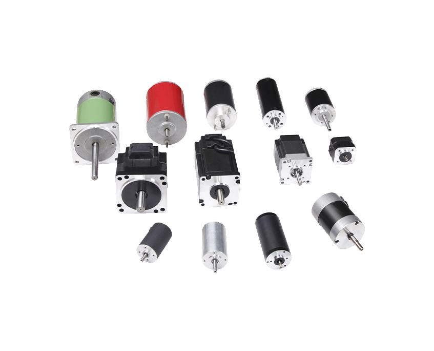
May 21,2026A DC gear motor is a self-contained electromechanical assembly that combines a direct current electric motor with an integrated mechanical gearbox, producing a single unit capable of delivering higher torque at lower output shaft speed than the motor alone could provide. The fundamental purpose of integrating a gearbox with a DC motor is to trade rotational speed for torque through gear reduction — a direct current motor spinning at 3,000–15,000 RPM in its natural state is fast and relatively weak in terms of rotational force, but after passing that rotation through a gearbox with a reduction ratio of 50:1 or 100:1, the output shaft spins at 60–150 RPM while delivering torque multiplied by the same ratio (minus efficiency losses). This speed-to-torque conversion is the defining characteristic that makes DC gear motors indispensable across an enormous range of mechanical applications.
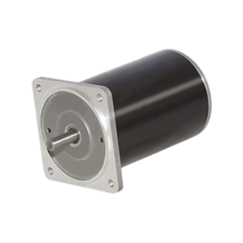
The DC motor element in a gear motor converts electrical energy from a direct current power source — which may be a battery, regulated DC power supply, solar panel system, or rectified AC supply — into rotational mechanical energy through electromagnetic interaction between the motor's stator field and rotor windings or permanent magnets. DC motors are particularly well suited to applications requiring variable speed and simple directional control, since both speed (through voltage or PWM signal adjustment) and direction (through supply polarity reversal) can be managed with straightforward electronics, making DC gear motors the natural choice for battery-powered, embedded system, and variable-speed mechatronic applications.
The gearbox component attached to the DC motor serves multiple functions beyond simple speed reduction. It also provides mechanical advantage that allows a smaller, lighter, and less expensive motor to perform work that would otherwise require a much larger direct-drive motor — reducing system cost, weight, and size simultaneously. In many applications, the gearbox also provides a degree of backdrive resistance (especially in worm gear configurations), meaning the load cannot easily back-drive the motor through the gearbox when power is removed, which is valuable in positioning, lifting, and holding applications where load-holding without continuous power draw is required.
Understanding how the motor and gearbox subsystems interact within a DC gear motor is essential for correctly interpreting performance specifications and predicting system behavior in a real application. The two subsystems are mechanically coupled through a shared shaft but have distinct operating characteristics that must be considered together.
The DC motor generates torque and speed according to its motor constant (Kv — back-EMF constant, expressed in RPM per volt) and its stall torque (the maximum torque the motor can produce at zero speed, limited by its electrical resistance and supply voltage). Between these two extremes, a DC motor operates along a torque-speed curve that is approximately linear — as the load torque increases, the speed decreases proportionally, and the current drawn from the supply increases. This relationship means that a DC gear motor running at no load spins close to its theoretical no-load speed, while a gear motor driving a heavy load at stall draws maximum current and produces maximum torque at zero speed. Understanding this torque-speed relationship is critical for sizing a DC gear motor correctly — selecting a motor whose rated operating point falls within the mid-range of its torque-speed curve ensures efficient operation and adequate thermal margin.
The gearbox transforms the motor's high-speed, low-torque output into the low-speed, high-torque output required by the application. The gear reduction ratio (N) determines the multiplication: output torque equals motor torque multiplied by N and by the gearbox mechanical efficiency (η), while output speed equals motor speed divided by N. A DC gear motor with a 100:1 planetary gearbox having 90% efficiency would therefore deliver 90 times the motor torque at 1/100th of the motor speed at the output shaft. This efficiency factor — typically 70–95% depending on gearbox type, number of stages, and operating conditions — means that real-world output torque is always somewhat lower than the theoretical gear ratio multiplication would suggest, and this efficiency loss appears as heat generated within the gearbox.
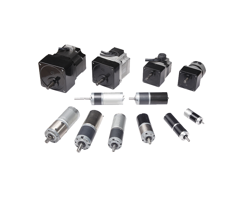
DC gear motors are built around several distinct DC motor technologies, each with different performance characteristics, control requirements, service life expectations, and cost profiles. Selecting the right motor type within the gear motor assembly is as important as selecting the gearbox configuration.
Brushed DC motors are the most common motor type found in DC gear motors, particularly in the cost-sensitive small and medium power ranges. They use a mechanical commutation system — carbon brushes pressing against a rotating copper commutator ring — to switch current direction in the rotor windings and maintain continuous rotation. Brushed DC gear motors are simple to control (speed is proportional to voltage; direction is determined by polarity), inexpensive to manufacture, and capable of high starting torque. The limitation of brushed motors is the wear of the carbon brush and commutator system — this mechanical contact creates a defined service life typically in the range of 500–3,000 hours depending on operating conditions, current levels, and motor design. Brush wear generates carbon dust that can cause problems in clean or food-grade environments, and brush arcing creates electromagnetic interference that must be managed in sensitive electronic systems.
Brushless DC gear motors replace the mechanical commutation of brushed motors with electronic commutation using Hall-effect sensors or back-EMF sensing to determine rotor position and switch current to the correct stator windings. Eliminating brush-commutator contact removes the primary wear mechanism of brushed motors, extending service life to 10,000–30,000 hours or more — a transformative advantage for applications requiring high reliability over long service periods. BLDC gear motors also run more quietly, generate less heat, and can achieve higher efficiency than equivalent brushed motors. The tradeoff is cost and control complexity — BLDC motors require an electronic motor controller (ESC or BLDC driver) rather than simple voltage application, adding both component cost and system complexity. For applications requiring long service life, high duty cycle operation, or operation in clean environments, the premium for BLDC gear motors is typically well justified.
Most small and medium DC gear motors use permanent magnet (PM) motor construction, where the stator field is provided by permanent magnets rather than wound field coils. PM DC motors are compact, efficient at partial loads, and have a linear torque-speed relationship that simplifies system modeling. The quality and grade of the permanent magnets used significantly influences motor performance — ferrite magnets are lower cost but produce lower flux density, while rare-earth magnets (neodymium-iron-boron, or NdFeB) produce significantly higher flux in a smaller volume, enabling more compact and higher-power-density gear motor designs. Premium DC gear motors for demanding applications typically use NdFeB magnets, while budget gear motors use ferrite magnets.
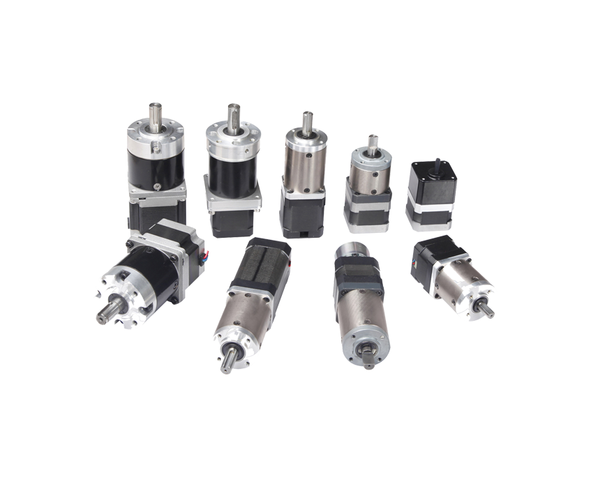
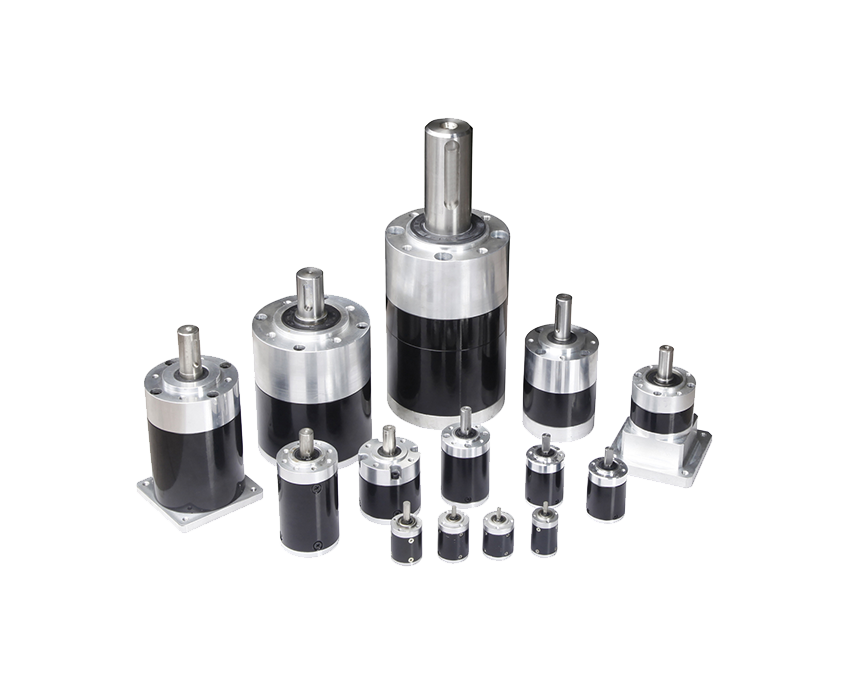
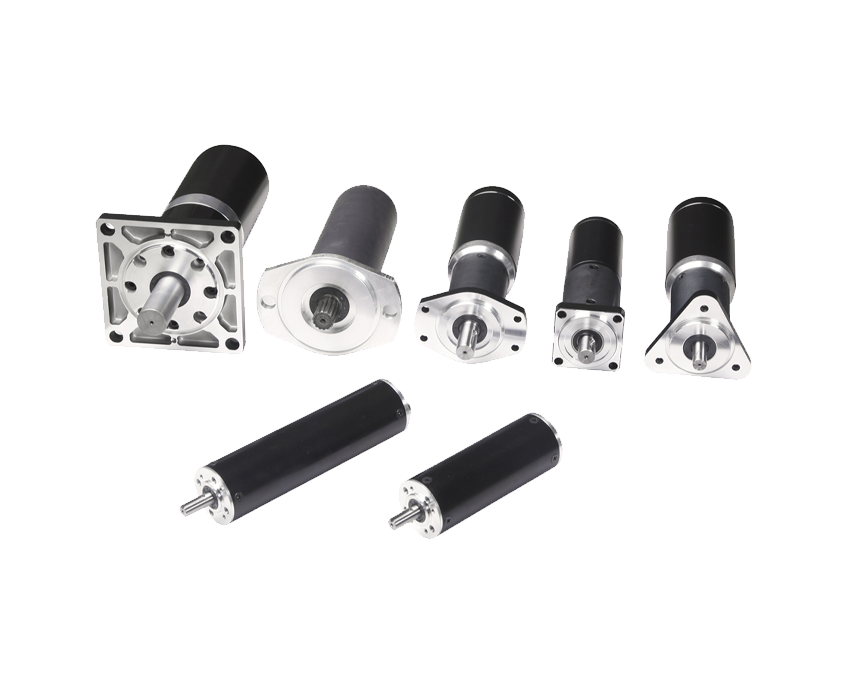
The gearbox integrated with the DC motor determines much of the gear motor's physical characteristics — including output torque capacity, backlash, backdrive resistance, noise level, efficiency, and physical form factor. Different gearbox types are suited to different application requirements, and understanding their trade-offs is essential for informed gear motor selection.
Planetary gearboxes are the premium choice for DC gear motors requiring high torque capacity in a compact form factor, low backlash, and high mechanical efficiency. The planetary arrangement — consisting of a central sun gear, multiple planet gears that orbit the sun gear while meshing with an outer ring gear, and a planet carrier that serves as the output — distributes the load across multiple gear meshes simultaneously. This load sharing allows planetary gearboxes to transmit much higher torques than equivalent-sized spur gearboxes while maintaining excellent concentric alignment of input and output shafts. Planetary DC gear motors are widely used in robotics, precision positioning, automation equipment, and any application where high torque density and low backlash are critical requirements. Multi-stage planetary gearboxes achieve reduction ratios from 3:1 up to 1000:1 or beyond by stacking multiple planetary stages in series, with each stage contributing to the total reduction and the overall efficiency being the product of each stage's individual efficiency.
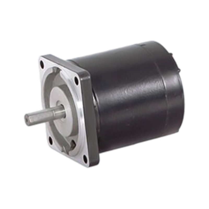
Spur gearboxes use a series of parallel-axis spur gears in a stepped-down arrangement to achieve speed reduction. They are the simplest and most cost-effective gearbox type, easy to manufacture to consistent tolerances, and capable of high efficiency (85–95% per stage) in clean, well-lubricated conditions. Spur DC gear motors are the standard choice for cost-sensitive applications where the higher torque density and concentric shaft arrangement of planetary designs are not required. They are widely used in consumer products, toys, home appliances, and general light industrial equipment. The limitation of spur gearboxes is that they carry load on a single tooth contact at each mesh point (unlike planetary designs), which limits their torque capacity for a given gear size, and they produce more noise than planetary designs due to the involute tooth contact pattern.
Worm gearboxes use a worm (a helical thread resembling a screw) meshing with a worm wheel (a gear with teeth angled to mesh with the worm helix) to achieve high reduction ratios in a single stage — typically 5:1 to 100:1 or more in a single mesh. The unique geometry of the worm gear produces a sliding rather than rolling contact between the worm and wheel, which generates more heat and lower efficiency than spur or planetary designs (typically 50–90% depending on reduction ratio and lead angle) but also creates the characteristic non-backdrivable property that makes worm DC gear motors invaluable for applications requiring load holding without power. A worm DC gear motor used in a valve actuator, conveyor gate, or lifting mechanism will hold its position when power is removed because the worm cannot be driven backward by the worm wheel under normal load conditions. This self-locking characteristic eliminates the need for a separate brake in many applications, simplifying system design and reducing cost.
Helical gear DC motors use gears with angled teeth that engage gradually along the tooth face, producing smoother and quieter operation than spur gears at the same speed and load — at a modest cost premium. Helical gearboxes are well suited to applications where noise is a primary concern, such as medical equipment, office automation, and consumer appliances. Bevel gearboxes use conically-shaped gears to change the output shaft direction by 90 degrees relative to the motor shaft — useful where the output motion must be perpendicular to the motor axis due to installation constraints. Bevel-helical combinations offer both directional change and smooth operation and are common in higher-end industrial DC gear motor configurations.
DC gear motor datasheets present a specific set of technical parameters that define the device's performance envelope. Interpreting these correctly is essential for confirming that a candidate motor meets the application's requirements before purchasing.
| Parameter | Typical Range | What It Defines | Why It Matters |
| Rated Voltage (V) | 3V – 48V DC | Nominal operating voltage | Must match power supply voltage |
| No-Load Speed (RPM) | 1 – 500 RPM (output) | Output speed at zero load | Upper speed limit at rated voltage |
| Rated Torque (N·m) | 0.01 – 500 N·m | Continuous safe output torque | Must exceed application load torque |
| Stall Torque (N·m) | 2–10× rated torque | Maximum torque at zero speed | Starting and peak load capacity |
| Rated Current (A) | 0.1 – 50A | Current at rated torque and speed | Determines power supply sizing |
| Gear Reduction Ratio | 3:1 – 1000:1 | Speed reduction factor | Sets output speed and torque multiplication |
| Gearbox Efficiency (%) | 50 – 95% | Mechanical power transmission efficiency | Affects actual output torque and heat |
| Backlash (arcmin / degrees) | 0.5° – 5° typical | Lost motion at direction reversal | Critical for positioning accuracy |
Selecting a DC gear motor correctly requires working through a systematic set of application requirements and matching them against available motor specifications. Rushing this process or selecting based on physical size alone is the most common cause of DC gear motor failures in engineering projects.
Begin by calculating the torque and speed required at the output shaft of the gear motor for your specific application. For rotating loads, torque is calculated from the force required multiplied by the lever arm distance (T = F × r). For lifting applications, torque equals the load weight multiplied by the spool or drum radius plus any friction and acceleration contributions. Once you have the required output torque and speed, calculate the required gear reduction ratio based on your available supply voltage and the typical motor speeds available in DC gear motors of the power range you're targeting. Add a safety factor of at least 1.5–2× to the required torque when selecting a motor to ensure adequate margin for start-up inertia, friction variation, and load variations during normal operation.
DC gear motor voltage ratings span from 3V (for miniature battery-powered applications) through 6V, 12V, 24V, and 48V to higher voltages for larger industrial gear motors. The supply voltage in your system determines which motor voltage range is appropriate. For battery-powered systems, 12V DC gear motors are the most common choice due to widespread availability of 12V batteries and power supplies; 24V DC gear motors are standard in industrial and automation applications where higher voltage reduces current for equivalent power, allowing smaller wire gauges and lower I²R losses over longer cable runs. Calculate the power requirement (P = T × ω, where ω is angular velocity in rad/s) and verify that the power supply can deliver the required current at the operating voltage with adequate headroom.
Match the gearbox type to the specific demands of your application rather than defaulting to whichever is cheapest. For robotics and precision positioning: planetary gearboxes with low backlash. For cost-effective general motion: spur gearboxes. For load-holding without continuous power: worm gearboxes. For quiet operation in sensitive environments: helical gearboxes. For perpendicular output shaft orientation: bevel gearboxes. Consider the duty cycle of the application — a gear motor driving a continuous-duty conveyor needs a thermal rating for sustained operation, while one used for intermittent actuation may operate safely at higher peak loads because of the cooling time between operations.
Physical installation constraints, environmental conditions, and interface requirements must all be verified before finalizing DC gear motor selection. Confirm that the output shaft diameter, length, and keyway dimensions are compatible with the driven component. Check the motor mounting face dimensions and bolt pattern against your mechanical design. If the gear motor will operate in a wet, dusty, or chemically aggressive environment, verify that the motor and gearbox IP protection rating is appropriate — IP54 is adequate for splash-proof indoor industrial use, while IP65 or IP67 is required for outdoor or washdown applications. For food processing or pharmaceutical applications, stainless steel housing and food-grade lubricant-filled gearboxes are necessary compliance requirements.
DC gear motors appear in an exceptionally wide range of products and systems, from miniature consumer devices to heavy industrial automation equipment. Understanding where and how they are used provides useful context for identifying the most appropriate product type and specification for a new application.
One of the most significant practical advantages of DC gear motors over AC motor systems is the simplicity and flexibility of their speed and direction control. The control approach differs between brushed and brushless DC gear motors, and selecting the appropriate control method for your application is an important part of the overall system design.
Pulse-width modulation (PWM) is the standard and most efficient method for controlling the speed of brushed DC gear motors. Rather than reducing motor voltage directly (which wastes energy as heat in a series resistor), PWM applies full supply voltage to the motor in rapid pulses, varying the duty cycle (the proportion of time the voltage is applied) to control average power delivery. At 50% duty cycle, the motor receives half the average voltage and runs at approximately half speed; at 100% duty cycle it runs at full speed. Modern motor driver ICs (such as the L298N, DRV8833, TB6612FNG, and many others) implement H-bridge circuits that provide both PWM speed control and direction control (forward/reverse) through simple logic signals from a microcontroller, making closed-loop DC gear motor speed control achievable with minimal external hardware.
Brushless DC gear motors require a dedicated electronic speed controller (ESC) or BLDC motor driver that manages the commutation sequence based on rotor position feedback from Hall-effect sensors or back-EMF sensing. These controllers handle the complex three-phase switching required to maintain continuous rotation in a brushless motor, presenting a simple speed reference input (analog voltage, PWM signal, or digital communication) to the user while managing the underlying commutation internally. Many modern BLDC motor controllers also incorporate field-oriented control (FOC) algorithms that optimize motor efficiency, torque response, and low-speed performance — particularly valuable for robotics and precision servo applications where smooth, high-bandwidth torque control is required.
DC gear motors are relatively low-maintenance devices, but appropriate care and systematic troubleshooting extend service life significantly and prevent avoidable failures in critical applications.
Twój adres e-mail nie zostanie opublikowany. Wymagane pola są zaznaczone *
Prawa autorskie © Zhejiang Dongzheng Motor Co., Ltd. Wszelkie prawa zastrzeżone.
 Producenci silników z przekładnią prądu stałego